CP2120 Просмотр технического описания (PDF) - Silicon Laboratories
Номер в каталоге
Компоненты Описание
производитель
CP2120 Datasheet PDF : 24 Pages
| |||
CP2120
5. SPI Slave Bus
The CP2120 provides a four-wire slave SPI interface. The CP2120's SPI Bus activates whenever the SPI Master
pulls the NSS pin low. The master can then clock data into the CP2120 through the Master-Out-Slave-In (MOSI)
pin and receive data from the CP2120 through the Master-In-Slave-Out (MISO) pin. The SPI Master provides the
SPI with a clock source. Figure 2 shows typical connections for an SPI bus.
SPI Master
SPICLK
CS
MISO
MOSI
SCLK
CS
CP2120
Figure 2. SPI Bus Typical Connections
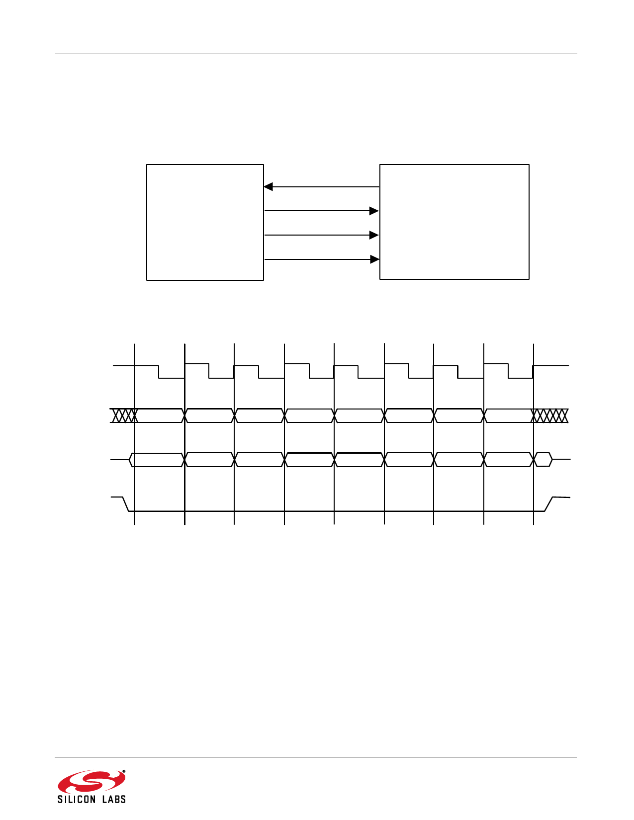
SCLK should be held high when idle. Figure 3 shows a CP2120 data transfer on the SPI Bus. If the CP2120 is the
only slave device on the SPI bus, the NSS pin can be tied low.
SCK
MOSI
MSB
Bit 6
Bit 5
Bit 4
Bit 3
Bit 2
Bit 1
Bit 0
MISO
MSB
Bit 6
Bit 5
Bit 4
Bit 3
Bit 2
Bit 1
Bit 0
NSS
Figure 3. Slave Mode Data/Clock Timing
Note: Some SPI clock speeds in the 100 kHz to 300 kHz range may result in communication issues. Moving the clock rate
faster or slower will resolve this problem.
Rev. 1.0
9
Share Link: 